2026-03-31
If you have any needs regarding SF6 gas recovery, purification, and recycling, please feel free to contact us using the information below! We offer high-quality, standardized SF6 gas processing equipment that ensures the purity of recycled SF6 gas and helps you save on the cost of purchasing new gas.
| Phone Number: | +86-0371-68988008 |
|---|---|
| Email: | [email protected] |
| Address: | High-new Tech Zone Zhengzhou, Henan, China |
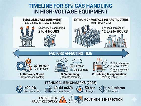
In the maintenance of high-voltage (HV) and extra-high-voltage (EHV) gas-insulated switchgear (GIS), “time is money.” Every hour of downtime translates to significant operational costs and grid instability. Understanding the timeline for SF6 gas handling is critical for project planning and regulatory compliance.
The duration of the recovery and refilling process is primarily determined by the gas volume of the equipment and the capacity of the recovery plant.
Small/Medium Equipment (e.g., 72.5kV to 110kV Breakers): Recovery and vacuuming typically take 2 to 4 hours.
High-Voltage Bays (e.g., 220kV GIS): A full gas cycle (recovery, vacuuming, and refilling) generally requires 6 to 10 hours.
Extra-High Voltage Infrastructure (e.g., 500kV GIS): Due to the immense gas volumes, the process can span 12 to 24+ hours, often requiring high-capacity, industrial-grade recovery units.
Three main technical phases dictate the speed of your SF6 maintenance:
Modern systems utilize high-flow, oil-free compressors.
Standard Performance: A 15 cubic meters per hour compressor is common for 110kV assets.
High-Efficiency Performance: For 500kV substations, a 30 to 60 cubic meters per hour compressor is the benchmark, drastically reducing the time needed to reach the required “negative pressure” (capturing the final grams of gas).
Before refilling, the equipment must be evacuated to remove air and moisture. This is often the longest phase.
The 1 mbar Threshold: To meet IEC 62271-4 standards, the vacuum pump must reach an ultimate pressure of less than 1 mbar (typically 0.1 mbar) to ensure the dielectric integrity of the new gas.
Ambient Temperature: In cold climates, moisture clings to the internal surfaces of the GIS, extending vacuum times.
Refilling is limited by the “freezing effect” (adiabatic cooling). As gas expands from the storage tank into the GIS, the temperature drops.
The Solution: Professional recovery units include a built-in vaporizer (typically 1.5 kW to 5 kW). This pre-heats the gas, allowing for a continuous, high-speed flow of 50 kg of SF6 in just 5 to 8 minutes without the risk of equipment freezing.
To optimize your SEO and operational performance, your equipment should meet these 2026-compliant benchmarks:
| Parameter | Performance Standard | Operational Benefit |
| Recovery Rate | Greater than 99.9% (to -1 mbar) | Zero emissions and maximum gas savings |
| Vacuum Pump Capacity | 40 – 64 cubic meters per hour | Faster moisture and air evacuation |
| Storage Pressure | 50 bar | High-density liquid storage for large volumes |
| Filtration Accuracy | 1 micron or less | Removes arc byproducts instantly |
Goal: Efficiency and precision.
Process: A PLC-controlled system automates the vacuum-to-refill transition, allowing technicians to focus on the mechanical inspection while the gas handling runs in the background.
Goal: Rapid restoration.
Process: High-power vaporization is used to refill the breaker at maximum speed. Meanwhile, integrated purification filters strip toxic SO2 and HF from the arced gas, making it immediately reusable for the next bay.
While a standard 220kV bay might take a full shift to process, the use of high-capacity, oil-free recovery plants can cut that time by up to 30%. By selecting equipment with integrated heating and high-flow compressors, utilities can ensure both regulatory compliance and maximum grid uptime.